

Power Factor Correction Philippines: Industrial Electrical Engineering
WHAT IS POWER FACTOR CORRECTION?
Power factor (PF) is the ratio of real power (kW) — power that performs actual useful work — to apparent power (kVA) — total power drawn from the distribution grid.
Power Factor = Real Power (kW) ÷ Apparent Power (kVA)
In a perfect electrical system, PF = 1.0. Every ampere drawn from MERALCO performs productive work — running motors, energizing heating elements, driving compressors. In the real industrial world, inductive loads cause current to lag behind voltage in phase. This phase displacement forces the facility to draw far more current from the grid than the actual work requires. The excess current is reactive power, measured in kVAR (kilovolt-ampere reactive) — it does no useful work, but it fully loads MERALCO’s cables, transformers, and substations. That is precisely why MERALCO penalizes you for generating it.
What creates low power factor in Philippine industrial facilities?
| Inductive Load Type | Power Factor Contribution |
|---|---|
| Three-phase induction motors (partial load) | Primary cause across all facility types |
| Industrial air compressors — reciprocating and screw-type | Dominant in garment, food processing, automotive |
| Welding machines and induction heaters | Dominant in metal fabrication |
| Fluorescent and HID lighting with magnetic ballasts | Significant in older industrial facilities |
| Power transformers at partial load | Present in every facility with multiple distribution transformers |
| Overhead cranes and hoists | Significant in warehousing and logistics |
| Centrifugal pumps with direct-drive coupling | Dominant in water treatment and cold storage |
| Elevator and escalator traction motors | Significant in commercial buildings |
Power factor correction is the deliberate injection of leading reactive power — supplied by capacitor banks — to cancel the lagging reactive power generated by these inductive loads. When capacitor kVAR offsets motor kVAR, net reactive demand drops, apparent power (kVA) falls, and MERALCO’s billing demand decreases.
The Power Triangle — Understanding the Geometry
| Component | Unit | What It Represents |
|---|---|---|
| Real Power | kW | Horizontal leg — actual work performed by the facility |
| Reactive Power | kVAR | Vertical leg — magnetizing current, no useful output, creates billing penalty |
| Apparent Power | kVA | Hypotenuse — what MERALCO meters and bills on demand tariffs |
| Power Factor | cos θ | Cosine of the angle between kW and kVA — higher is better; 1.0 is ideal |
Adding capacitor kVAR shrinks the vertical leg. As reactive power falls, apparent power falls, the angle narrows, and power factor rises toward 1.0.
MERALCO’s Power Factor Clause — The Exact Billing Mechanism
For General Service Demand (GSD) and Large Power (LP) rate accounts, MERALCO applies the following automatic billing adjustment when average monthly PF falls below 0.85 lagging:
Adjusted Billing kW = Measured kW Demand × (0.85 ÷ Actual PF)
This adjustment is automatic. It requires no inspection, no notice, and no dispute to trigger. It compounds across every demand-linked charge on the bill — generation demand, distribution demand, transmission demand, metering charge, and system loss charge.
Financial Impact — Taytay Industrial Cold Storage: Real Numbers
| Parameter | Before Correction | After Correction |
|---|---|---|
| Measured Real Power Demand | 600 kW | 600 kW |
| Actual Power Factor | 0.69 | 0.94 |
| MERALCO Adjustment Factor | 0.85 ÷ 0.69 = 1.232 | No adjustment — PF > 0.85 |
| Billing kW Demand | 739 kW | 600 kW |
| Phantom kW Billed | +139 kW | — |
| Monthly Demand Surcharge (@₱480/kW) | ₱66,720/month | ₱0/month |
| Annual Penalty Cost | ₱800,640 | ₱0 |
| Capacitor System Investment | — | ₱450,000 – ₱650,000 |
| Simple Payback Period | — | 7 – 10 months |
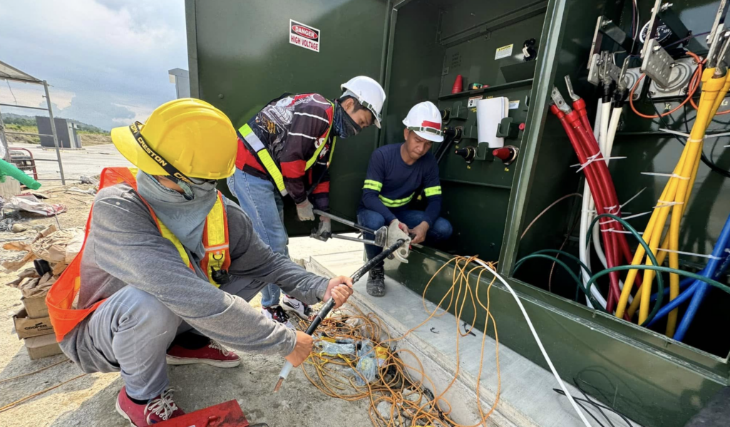
THREE-AGENCY REGULATORY FRAMEWORK
Power factor correction in the Philippines is governed by three independent regulatory authorities. Most facility managers are aware of only MERALCO. Full legal compliance requires satisfying all three simultaneously — and each operates its enforcement track without coordinating with the others.
| Regulatory Authority | Role in PF Compliance | Specific Requirement | Consequence of Non-Compliance |
|---|---|---|---|
| MERALCO(Electric Distribution Utility) | Billing enforcement via power factor clause in GSD and LP rate schedules | Average monthly PF must be ≥ 0.85 lagging, measured at the main billing meter every billing period without exception | Automatic upward billing demand adjustment each month PF < 0.85; potential supply termination for LP accounts with chronic non-compliance |
| Department of Energy (DOE) | Regulatory authority under RA 11285 — Energy Efficiency and Conservation Act of 2019 | Designated Establishments (DEs) consuming ≥ 500,000 kWh/year must file a Philippine Energy Management Plan (PEMP) every three years; reactive power / PF improvement is a mandatory documented measure | Administrative fines up to ₱1,000,000 per year per violation; suspension of Certificate of Energy Compliance; public disclosure on DOE’s website |
| LGU Building Official / DOLE | Local electrical permit authority (LGU) and occupational safety enforcement (DOLE) | Electrical permit from LGU Building Official; SLD signed by PRC-licensed PEE; installation supervised by licensed Master Electrician; Certificate of Final Electrical Inspection (CFEI) issued by LGU Electrical Inspector; DOLE OSHS compliance per RA 11058 and DO 198-18 | Illegal installation; no valid CFEI; DOLE stop-work order; insurance policy invalidation; MERALCO may decline to officially credit PF improvement without valid permit documentation |
The Critical Field Reality: MERALCO does not verify whether you hold a valid electrical permit or a DOE-compliant PEMP before applying the power factor billing surcharge. The LGU does not check your MERALCO history before issuing a permit. DOE does not verify MERALCO compliance before auditing your PEMP. All three regulatory tracks run independently. Satisfying one does not satisfy the others. Full legal protection and complete billing relief require satisfying all three.
▌ WHO IS REQUIRED TO INSTALL POWER FACTOR CORRECTION?
Legally Compelled by MERALCO Rate Schedule
- General Service Demand (GSD) accounts — commercial and light-industrial facilities on demand billing with connected loads above 5 kVA; the power factor clause activates automatically when average monthly PF falls below 0.85
- Large Power (LP) accounts — major industrial consumers; the PF clause is strictly and consistently enforced; MERALCO LP account representatives conduct periodic power quality assessments at LP premises
- Time-of-Use (TOU) rate customers — PF correction is especially critical during on-peak billing windows when demand charges are at their maximum; PF deviations during peak hours produce disproportionately large surcharges versus off-peak periods
Financially Urgent Even Without an Active MERALCO Penalty
- Facilities averaging PF between 0.85 and 0.92 — technically penalty-free, but operating with 8–15% less usable transformer capacity and cable current-carrying capacity than the hardware nameplate rating allows
- Facilities planning a load expansion — raising PF from 0.83 to 0.94 before adding new machinery provides 13–15% additional effective transformer capacity at zero transformer capital cost
- DOE Designated Establishments with a PEMP filing due — reactive power correction delivers the most measurable, most directly quantifiable energy savings data of any measure available in a PEMP submission
High-Risk Facility Types — Rizal Province and Luzon
| Facility Type | Typical Uncorrected PF Range | Primary Inductive Load Source |
|---|---|---|
| Garment and textile manufacturing | 0.60 – 0.75 | Sewing machine motors, industrial compressors, HVAC units |
| Cold storage and industrial refrigeration | 0.68 – 0.82 | Multi-compressor banks, condenser fans, cooling tower pumps |
| Metal fabrication, welding, CNC machine shops | 0.55 – 0.72 | Arc welders, induction heaters, spindle motors, overhead cranes |
| Water treatment and pumping stations | 0.72 – 0.84 | Centrifugal pumps, submersible motors, aerator blowers |
| Printing, packaging, and converting plants | 0.68 – 0.80 | Press motors, hydraulic drives, conveyor systems |
| Commercial malls and office towers | 0.78 – 0.88 | Centrifugal chiller motors, escalators, elevator traction drives |
| Hospitals and medical centers | 0.75 – 0.87 | HVAC systems, medical imaging, sterilization equipment |
| Data centers and telecom facilities | 0.80 – 0.90 | UPS rectifiers, precision cooling, power distribution units |
| Food processing plants | 0.65 – 0.80 | Conveyor motors, blast freezer compressors, mixing and blending drives |
▌ TECHNICAL BREAKDOWN: TWO SYSTEMS OF POWER FACTOR CORRECTION
◉ SYSTEM 1 — FIXED CAPACITOR BANKS (STATIC CORRECTION)
Fixed capacitor banks are permanently energized units that supply a constant, unchanging kVAR output to the facility electrical system regardless of load variation. They are the simplest, most mechanically reliable, and most cost-effective correction technology — and the engineering-correct solution for facilities whose reactive load is stable and predictable across all operating conditions and shifts.
Operating Principle
A fixed bank connects to the main switchboard or motor control center via a dedicated circuit breaker, disconnect switch, and overcurrent protection. Once energized, it continuously injects leading reactive current at a fixed level around the clock. Because output is constant, fixed banks must be sized for the minimum baseline reactive load — not the peak. Sizing for peak load and then running during off-peak hours creates leading power factor (PF > 0.85 leading) — which MERALCO penalizes identically to lagging PF.
Best Applications
- Cold storage with near-continuous compressor operation at steady load
- Municipal and industrial pumping stations operating 24/7 at a fixed duty point
- Individual motor correction for large, permanently running motors (≥ 22 kW / 30 HP)
- Single-shift manufacturing with highly consistent load profiles confirmed by 7-day measurement
PEC 2017 Compliance Requirements — Fixed Capacitor Banks
| PEC Requirement | Article Reference | Specification |
|---|---|---|
| Disconnecting means rating | Art. 4.60.5 | Minimum 135% of capacitor rated current |
| Overcurrent protection | Art. 4.60.6 | Maximum 250% of rated current; dedicated circuit breaker; separate from motor protection |
| Discharge means | Art. 4.60.7 | Discharge resistors required; terminal voltage must reach ≤ 50V within 60 seconds of de-energization |
| Conductor sizing | Art. 2.10 | Minimum 135% of rated capacitor current for continuous duty |
| Grounding | Art. 2.50 | Capacitor cases, frames, and enclosure bonded to main ground bus |
kVAR Sizing Formula
kVAR Required = kW Demand × (tan θ₁ − tan θ₂)
Where: θ₁ = arccos(existing measured PF) · θ₂ = arccos(target PF) · kW = 7-day measured average real power demand
Worked Example — Welding and Fabrication Shop, Antipolo City, Rizal
| Variable | Value |
|---|---|
| 7-day average real power demand | 280 kW |
| Measured average power factor | 0.68 |
| Target power factor | 0.93 |
| θ₁ = arccos(0.68) = 47.16° → tan = | 1.078 |
| θ₂ = arccos(0.93) = 21.57° → tan = | 0.395 |
| kVAR Required = 280 × (1.078 − 0.395) | = 191 kVAR |
| Specified configuration | 4 × 50 kVAR steps = 200 kVAR |
◉ SYSTEM 2 — AUTOMATIC POWER FACTOR CORRECTION (APFC)
An Automatic Power Factor Correction system uses a microprocessor-based controller to monitor the facility’s real-time power factor and automatically switch capacitor bank steps in or out — maintaining a programmed target of 0.92–0.95 lagging regardless of how the facility’s load changes throughout the operating day or across shifts.
Operating Principle
A current transformer (CT) on the main incomer phase conductor feeds current and voltage signals continuously to the APFC controller. The controller computes real-time PF, compares it to the setpoint, and commands contactors to energize or de-energize capacitor steps. A programmable switching delay — typically 45–60 seconds between step events — prevents hunting (rapid oscillating switching) that destroys contactors prematurely.
Best Applications
- Multi-shift manufacturing with significant load variation between production, maintenance, and idle periods
- Plants where the number of operating machines varies continuously throughout the day
- Mixed-load facilities with both steady base loads and highly intermittent peak loads
- Facilities undergoing load expansion where future kVAR demand is uncertain
- Any facility where the 7-day audit reveals PF variance greater than ±0.08 across the monitoring period
APFC System Component Specification — Philippine Market
| Component | Technical Specification | Philippine Market Notes |
|---|---|---|
| APFC Controller / Relay | 6–16 step capacity; programmable PF setpoint (0.01 resolution); anti-hunting logic; RS-485 Modbus for SCADA | Brands: Electronicon, Lovato, Ducati Energia, ABB RVT — available at Manila and Mandaluyong distributors |
| Capacitor Steps | Self-healing polypropylene film; IEC 60831-1 compliant; 440V AC ± 10% minimum rated | Philippine distribution voltage regularly spikes 415–425V; 380V-rated units fail within 12–18 months under local grid conditions |
| Contactors | Capacitor-duty rated — AC6b duty class ONLY; surge-suppressed; rated for capacitor inrush currents | Standard AC3 motor contactors weld shut from capacitor switching transients within 6–24 months without exception |
| Current Transformer (CT) | 5A secondary; accuracy class 1.0 minimum; matched to incomer conductor size and controller input range | CT ratio error is the single most common cause of APFC system malfunction — hunting, overcorrection, or complete failure to correct |
| Detuned Reactors | Series-connected per capacitor step; p-factor matched to facility harmonic profile | Mandatory in every facility with VFDs, inverter-type AC, UPS systems, or switching power supply loads |
| Surge Arresters | Class II MOV-type; rated for local distribution nominal voltage | Mount at APFC panel incomer — Philippine grid switching transients are frequent and capacitor-destructive |
| Enclosure | IP42 (enclosed MCC room) · IP54 (factory floor) · IP65 (outdoor or high-humidity) | Powder-coated mild steel standard; stainless steel for coastal, high-salinity, or chemically active environments |
▌ SPECIFICATION AND SIZING TABLES
TABLE 1 — kVAR Multiplier Reference
Required kVAR = Facility kW Demand × Multiplier from table
| Existing PF ↓ | Target 0.90 | Target 0.92 | Target 0.95 | Target 0.97 |
|---|---|---|---|---|
| 0.55 | 1.127 | 1.185 | 1.283 | 1.361 |
| 0.60 | 0.849 | 0.907 | 1.005 | 1.083 |
| 0.65 | 0.714 | 0.772 | 0.870 | 0.948 |
| 0.68 | 0.643 | 0.701 | 0.799 | 0.877 |
| 0.70 | 0.591 | 0.649 | 0.747 | 0.825 |
| 0.72 | 0.540 | 0.598 | 0.696 | 0.774 |
| 0.75 | 0.477 | 0.535 | 0.633 | 0.711 |
| 0.78 | 0.416 | 0.474 | 0.572 | 0.650 |
| 0.80 | 0.375 | 0.433 | 0.531 | 0.609 |
| 0.83 | 0.307 | 0.365 | 0.463 | 0.541 |
| 0.85 | 0.265 | 0.323 | 0.421 | 0.499 |
| 0.88 | 0.184 | 0.242 | 0.340 | 0.418 |
Usage: 350 kW facility at 0.72 existing PF targeting 0.95 → 350 × 0.696 = 244 kVAR required
TABLE 2 — Detuned Reactor Selection by Harmonic Profile
| Facility Harmonic Environment | THDv at Incomer | Recommended p-Factor | Tuned Frequency | Typical Facility Type |
|---|---|---|---|---|
| Linear loads only — no VFDs or inverters | < 3% | p = 5.67% | 210 Hz (below 5th harmonic) | Simple pumping stations, cold storage, resistive heating |
| Limited VFDs or small inverters | 3% – 8% | p = 7% | 189 Hz | Light manufacturing, garment, mixed commercial |
| Multiple VFDs, UPS systems, inverter AC | 8% – 15% | p = 14% | 134 Hz | CNC shops, printing plants, data centers |
| Arc furnaces, large rectifiers | > 15% | Active Harmonic Filter required — consult PEE | N/A | Steel foundries, electroplating, smelting |
TABLE 3 — APFC Step Configuration by Facility Demand
| Facility Demand Range | Recommended Steps | Step Size | Total kVAR Range | Controller Specification |
|---|---|---|---|---|
| 50 – 150 kW | 4 – 6 steps | 15 – 25 kVAR/step | 60 – 150 kVAR | 6-step relay, basic |
| 150 – 400 kW | 6 – 8 steps | 25 – 50 kVAR/step | 150 – 400 kVAR | 8-step relay, Modbus-capable |
| 400 – 800 kW | 8 – 12 steps | 50 – 75 kVAR/step | 400 – 900 kVAR | 12-step relay, remote monitoring |
| > 800 kW | Hybrid fixed base + 12–16-step APFC | 75 – 100 kVAR/step | 600 – 1,600 kVAR | 16-step relay with SCADA integration |
▌ STEP-BY-STEP INSTALLATION PROCESS
A compliant, fully functional power factor correction system in the Philippines requires the following eight-phase sequence. Deviating from this sequence — most critically by skipping Phases 1, 3, and 7 — accounts for the overwhelming majority of failed and underperforming installations across Rizal Province and Metro Manila industrial facilities.
PHASE 1 — POWER QUALITY BASELINE AUDIT
Duration: 7–14 days continuous logging
Deploy a calibrated Class A power quality analyzer (IEC 61000-4-30 compliant — Fluke 435-II or Hioki PQ3198) at the main MERALCO billing meter incomer. Log continuously for a minimum of 7 consecutive days capturing at least one full production cycle: peak shift, off-shift, maintenance windows, and any weekend or scheduled shutdown.
Required measurements from the 7-day log:
- Average, minimum, and maximum power factor at 1-minute logging intervals across the full period
- Real power (kW), reactive power (kVAR), and apparent power (kVA) demand by hour — complete profile
- Total harmonic distortion: voltage (THDv) and current (THDi), measured by harmonic order at incomer
- Voltage unbalance and frequency deviation across the measurement period
- Complete inventory of all existing reactive power compensation anywhere in the facility
This step cannot be replaced by reading the MERALCO bill. Billing statements show the average PF for the billing period — not PF distribution by hour or by shift. A system sized from the bill alone allocates the wrong number of steps for the actual operating profile, potentially overcorrects during off-peak hours, and consistently under-delivers projected billing savings.
PHASE 2 — ENGINEERING DESIGN
Duration: 5–10 working days after measurement completion
A PRC-licensed Professional Electrical Engineer prepares:
- Hourly kW, kVAR, and kVA load profile charts across the full 7-day monitoring period
- Required kVAR calculation — formula method applied to the worst-case operating load condition
- Configuration decision: fixed bank vs. APFC vs. hybrid (fixed base kVAR + APFC stepped overlay)
- Number of APFC steps and step size — optimized against the full load profile spread
- Detuned reactor p-factor selected from harmonic spectrum analysis results
- CT ratio specification and APFC controller model selection and programming parameters
- Single-line diagram (SLD) of the proposed installation — signed and sealed by PEE
- Equipment specification schedule and complete bill of materials
- Panel layout and dimensional drawing for LGU permit submission
PHASE 3 — HARMONIC RESONANCE ANALYSIS
Required whenever THDv > 3% or THDi > 8% at the incomer
Calculate the natural resonant frequency of the proposed capacitor bank with the existing electrical system impedance:
f_res = f_fundamental × √(kVA_transformer ÷ kVAR_capacitors)
Example — 750 kVA transformer, 150 kVAR proposed bank:
f_res = 60 × √(750 ÷ 150) = 60 × 2.236 = 134 Hz — coincides with 3rd harmonic — detuned reactors mandatory
If the resonant frequency falls within ±15% of any dominant harmonic order (3rd = 180 Hz, 5th = 300 Hz, 7th = 420 Hz at 60 Hz system frequency), detuned reactors are mandatory to shift the resonant point safely below the lowest dominant harmonic present.
PHASE 4 — EQUIPMENT PROCUREMENT
Begin immediately after engineering design is finalized — do not wait for the permit
| Equipment | Local Availability | Lead Time |
|---|---|---|
| Fixed capacitor banks ≤ 150 kVAR | Locally stocked — Manila / Cebu distributors | 1 – 2 weeks |
| Name-brand APFC controllers | Limited local stock | 2 – 4 weeks |
| Detuned reactors | Predominantly imported — Europe / Taiwan | 4 – 8 weeks |
| Capacitor-duty contactors (AC6b) | Locally stocked | 1 – 2 weeks |
| Surge arresters and CTs | Locally stocked | 1 week |
| Custom APFC panel fabrication | Local — Antipolo / Cainta fabricators | 3 – 5 weeks |
Total timeline from design to installation readiness: 8–12 weeks for a full APFC system with detuned reactors. Begin procurement on the day the SLD is finalized. Budget 3–4 months of continued MERALCO penalties in the project ROI calculation.
PHASE 5 — ELECTRICAL PERMIT APPLICATION
Submit immediately upon design finalization — runs in parallel with procurement
Documents for LGU Building Official of Antipolo, Cainta, Taytay, or relevant municipality:
- Electrical Permit Application Form — signed by facility owner or authorized representative
- Single-Line Diagram — signed and sealed by PRC-licensed PEE
- Bill of Materials and Technical Specification Schedule
- PRC License and Professional Tax Receipt (PTR) — PEE and Master Electrician
- Copy of existing Certificate of Electrical Inspection for the main facility installation
- Location / site plan showing APFC panel mounting location
LGU processing time: 5–15 working days depending on backlog. Submit simultaneously with procurement launch.
PHASE 6 — INSTALLATION
- Implement full Lockout/Tagout (LOTO) on main switchboard incomer — verify absence of voltage with calibrated instrument before any work begins; post LOTO tags at all energy isolation points
- Mount APFC panel at designated location — verify minimum 1.0 meter clear working space in front per PEC Article 1.10
- Install CT on incomer phase conductor — confirm polarity marking orientation, nameplate ratio, and core clamp torque
- Run power cables from main bus to APFC panel incomer — minimum 135% of capacitor rated current for continuous duty sizing
- Wire capacitor steps to contactors; install detuned reactors in series before each capacitor bank (reactor → capacitor, not capacitor → reactor)
- Wire APFC controller: CT secondary to current input terminals; phase voltage to voltage input; confirm correct phase-to-phase alignment
- Mount and wire surge arrester at APFC panel incomer — between main breaker and main busbar
- Ground all capacitor cases, reactor frames, contactor frames, and panel enclosure to facility main ground bus — verify continuity with low-resistance ohmmeter
- Install discharge resistors across each capacitor step — post 60-second discharge warning notice on panel interior door
- Apply all cable identification tags, circuit labels, arc-flash warning notice, LOTO procedure card inside panel door — per PEC and DOLE OSHS requirements
PHASE 7 — COMMISSIONING AND TESTING
Pre-energization checks:
- Insulation resistance test (megohmmeter) — each capacitor step phase-to-ground and phase-to-phase: minimum 100 MΩ at 500V DC
- CT circuit continuity — confirm no open-circuit condition on CT secondary; open CT secondary produces dangerous high voltage across CT terminals
- Verify APFC controller wiring phase alignment — current and voltage inputs must reference the same phase; phase reversal produces inverted PF readings
- Program APFC controller: target PF = 0.92–0.95; switching delay = 45–60 seconds minimum; CT ratio = exact nameplate value; step size = actual measured kVAR per step
Post-energization verification:
- Confirm APFC controller PF display matches independent clamp meter reading at incomer — within ±0.02
- Manual step-through of every capacitor step — confirm contactor pick-up, no chatter, stable holding, correct kVAR contribution
- Infrared thermography scan of all panel connections — performed within first 45–60 minutes of full-load operation
- Record and report pre-installation vs. post-installation power factor at main billing meter — required for commissioning report and MERALCO documentation
PHASE 8 — DOCUMENTATION AND BILLING VERIFICATION
- Obtain Certificate of Final Electrical Inspection (CFEI) from LGU Electrical Inspector — schedule immediately after commissioning
- Prepare and submit as-built SLD reflecting actual installation — signed and sealed by PEE
- Compile test report package: megger results, CT ratio verification, commissioning PF measurements, infrared thermography scan images
- For DOE Designated Establishments: prepare PEMP addendum with before/after power quality data, annual kVAR reduction, and equivalent kWh savings using DOE’s prescribed system loss factor
- Pull the first post-installation MERALCO bill — verify average PF ≥ 0.85, confirm the demand adjustment line item is eliminated, calculate actual savings versus projected savings from the engineering report
▌ PRE-INSTALLATION CHECKLIST
Complete all items before engineering design is submitted to the LGU. Unchecked items are the leading cause of substandard results, project delays, and continued MERALCO penalties after a system is commissioned.
Power Quality Assessment
- 7-day power quality log completed at main billing meter incomer — calibrated Class A analyzer, IEC 61000-4-30 compliant
- Average monthly PF reviewed from minimum 12 consecutive months of MERALCO billing statements
- THDv and THDi measured and recorded at incomer — harmonic spectrum by order documented
- Load profile by hour documented across all production shifts including weekends and any scheduled shutdown periods
- All existing capacitor banks located, rated, and mapped on the existing single-line diagram
- All VFDs, UPS systems, inverter-type air conditioning, and rectifier loads inventoried with kVA rating and facility location
- Main transformer nameplate data collected: kVA rating, impedance (%Z), voltage ratio — required for resonance frequency calculation
Engineering Design Verification
- Required kVAR calculated from 7-day measured data — NOT from MERALCO billing demand figure alone
- Fixed vs. APFC vs. hybrid configuration decision documented with written technical justification
- Resonant frequency calculation completed — confirmed no coincidence with any dominant harmonic order in measured spectrum
- Detuned reactor p-factor selected and specified based on measured harmonic spectrum (not assumed)
- CT ratio verified to match APFC controller secondary input range and incomer conductor cross-section
- Single-line diagram completed, signed, and sealed by PRC-licensed PEE
Regulatory and Legal Compliance
- Electrical permit application submitted to LGU Building Official of the relevant municipality
- PEE current PRC license and PTR confirmed — within active renewal period
- Master Electrician current license and PTR confirmed
- DOLE OSHS requirements reviewed — RA 11058 and DOLE DO 198-18 provisions applicable to electrical installation
- DOE Designated Establishment status confirmed — PEMP filing obligation assessed and noted
- MERALCO account classification confirmed: GSD / LP / TOU — applicable power factor clause verified
Equipment Verification
- Capacitors specified at 440V AC minimum — IEC 60831-1 compliant, self-healing polypropylene film type — NOT 380V or 415V rated units
- Contactors are capacitor-duty rated: AC6b duty class — NOT standard AC3 motor contactors
- Discharge resistors included in bill of materials for every capacitor step in the system
- Surge arresters (Class II, MOV-type) included at APFC panel incomer
- APFC controller supports required number of steps; anti-hunting logic confirmed in manufacturer’s specification sheet
- Enclosure IP rating confirmed appropriate for the specific installation environment
- Detuned reactors: p-factor, voltage rating, and kVAR rating specified and confirmed compatible with paired capacitor steps
Installation Safety Readiness
- APFC panel mounting location confirmed — 1.0m minimum working clearance physically verified on site
- Cable routing path identified, measured, and confirmed obstruction-free
- LOTO procedure documented in writing — safety officer briefed before any work commences
- Capacitor discharge protocol (60-second minimum wait after de-energization) posted inside panel door before energization
- PPE requirements for work near energized capacitor terminals defined and procured
▌ TOP 10 POWER FACTOR CORRECTION VIOLATIONS IN PHILIPPINE INDUSTRIAL FACILITIES
Based on ETCZ Corp engineering assessments and commissioning inspections across Antipolo, Cainta, Taytay, and the wider Luzon industrial corridor
| Rank | Violation | Frequency | Risk Level | Documented Field Consequence |
|---|---|---|---|---|
| 1 | Bank sized from MERALCO bill alone — no 7-day measured power quality data | ★★★★★ | High | Overcorrection or under-correction; continued MERALCO penalty or new leading PF surcharge created by the “correction” itself |
| 2 | No detuned reactors in VFD-heavy or harmonic-rich facility | ★★★★★ | Critical | Harmonic resonance amplification; capacitor bank destroyed within months; harmonic damage cascades to other equipment across the facility |
| 3 | Standard AC3 motor contactors used for capacitor switching duty | ★★★★☆ | High | Contact welding within 6–24 months; APFC loses steps silently; billing penalty returns undetected — sometimes for multiple billing cycles |
| 4 | Overcorrection producing leading power factor (PF > 0.85 leading) | ★★★★☆ | High | MERALCO leading PF surcharge equal to or greater than original lagging PF penalty; voltage rise; risk of forced utility disconnection of capacitor bank |
| 5 | APFC controller programmed to unity target (1.0) instead of 0.92–0.95 | ★★★☆☆ | High | Continuous hunting; leading PF at every partial-load period; accelerated contactor wear; premature total system failure |
| 6 | Incorrect CT ratio entered into APFC controller | ★★★☆☆ | High | Controller reads wrong power factor; system oscillates continuously or refuses to engage; billing penalty persists through months of apparent operation |
| 7 | No LGU electrical permit obtained for capacitor bank installation | ★★★☆☆ | Medium | Illegal installation; no valid CFEI; DOLE citation and potential stop-work order; insurance policy gap; DOE compliance deficiency |
| 8 | Discharge resistors omitted from installation | ★★★☆☆ | Critical | Capacitor terminals retain stored charge at full voltage after de-energization; severe electric shock or electrocution risk to any maintenance personnel who touch terminals within the first minute |
| 9 | Individual motor capacitors oversized beyond motor no-load kVAR limit | ★★☆☆☆ | Critical | Motor self-excitation on shutdown; runaway terminal voltage; insulation breakdown; winding failure and fire risk |
| 10 | No post-commissioning MERALCO billing verification | ★★☆☆☆ | Medium | Failed or degraded system goes undetected; billing penalty continues for multiple billing cycles; client pays for a correction system delivering zero financial benefit |
▌ BUDGET REFERENCE TABLE
Philippine market pricing — Rizal Province and Metro Manila — 2026. Inclusive of engineering design, equipment supply, full installation, LGU permit processing, and commissioning. Excludes VAT.
| System Configuration | Facility Scale | kVAR Range | Total Installed Budget | Simple Payback (Typical) |
|---|---|---|---|---|
| Fixed capacitor bank — single step, wall-mounted | Small commercial / light industrial | 25 – 75 kVAR | ₱45,000 – ₱95,000 | 6 – 12 months |
| Fixed capacitor bank — panel-type, 2–3 steps | Small-to-medium industrial | 75 – 200 kVAR | ₱90,000 – ₱220,000 | 10 – 18 months |
| APFC system — 6-step, no detuned reactors | Medium industrial, low-harmonic loads | 100 – 300 kVAR | ₱160,000 – ₱380,000 | 12 – 20 months |
| APFC system — 8–12 step with detuned reactors | Medium-large industrial, VFD loads present | 200 – 600 kVAR | ₱320,000 – ₱750,000 | 14 – 24 months |
| Hybrid fixed base + APFC stepped overlay | Large multi-shift industrial | 400 – 900 kVAR | ₱480,000 – ₱1,100,000 | 14 – 22 months |
| APFC with active harmonic filter integration | Heavy industrial, severe harmonic environment | 300 – 800 kVAR | ₱600,000 – ₱1,500,000 | 18 – 36 months |
| Individual motor correction (per motor ≤ 30 HP) | Any facility type, applied per motor | 5 – 20 kVAR/motor | ₱8,000 – ₱25,000/motor | 6 – 14 months |
Facilities averaging PF below 0.70 reach payback at the lower end of each range. MERALCO Time-of-Use accounts with on-peak demand surcharges see accelerated payback of 8–14 months regardless of system configuration.
▌ 10 INSIDER TIPS FROM ETCZ CORP ENGINEERS
TIP #1 — Pull Twelve Months of MERALCO Bills Before Contacting Any Contractor
Your MERALCO billing statement for GSD and LP accounts lists your “Average Power Factor” in the billing data summary. Before any contractor visits your facility, collect the last twelve months of bills and record the monthly PF figure for each month. This gives you two critical data points no contractor can estimate without them: whether your penalty is seasonal or year-round, and the precise average monthly cost of the problem you are trying to solve. Any contractor who proposes a correction system without reviewing your billing history first is operating on assumptions, not engineering.
TIP #2 — Never Accept a System Sized From Your MERALCO Bill Alone
The billing demand on your MERALCO statement represents an average across the entire billing period. Sizing a capacitor bank to match that average misses the full operating picture entirely. A factory running at 0.65 PF during peak production and 0.89 PF during the night shift requires fundamentally different engineering than one holding a steady 0.75 PF all day across all shifts. The only defensible basis for correct kVAR sizing is 7 days of continuously logged power quality data from a calibrated instrument — never a single billing figure, and never a contractor’s visual estimate.
TIP #3 — Detuned Reactors Are Mandatory in Any Modern Philippine Industrial Facility
If your facility operates VFDs, inverter-type air conditioning, UPS systems, or LED driver systems at material scale, harmonic distortion exists on your electrical network. Capacitors are inherently low-impedance paths for harmonic currents — without detuned reactors in series, the capacitor bank draws far more harmonic current than its thermal design allows, overheats, degrades, and fails. In ETCZ Corp field inspections across Rizal Province and Metro Manila, over 65% of VFD-equipped industrial facilities that installed capacitor banks without detuned reactors experienced confirmed capacitor failure within 18 months of commissioning.
TIP #4 — Set Your APFC Controller to 0.93, Never to 1.0
MERALCO’s billing penalty threshold is 0.85. Targeting unity PF (1.0) is engineering overkill that creates a new operational hazard: leading power factor at every partial-load period — nights, shift changes, production slowdowns, shutdowns. Capacitors continue injecting kVAR after inductive loads de-energize, and MERALCO’s leading PF penalty is symmetric with the lagging PF penalty you were trying to eliminate. Set the APFC controller target to 0.92–0.95 lagging. This provides 7–10 percentage points of headroom above the 0.85 penalty threshold, with measurement tolerance margin, while keeping the system safely lagging at all load conditions.
TIP #5 — Eliminate Phantom Reactive Loads Before You Size the Correction System
Before finalizing kVAR requirements, walk the facility during off-hours with a clamp meter and identify motors running at no load: fans cycling without air handling duty, compressors idling with no pneumatic demand, conveyor drives energized but carrying nothing, HVAC units conditioning unoccupied spaces. Induction motors draw nearly the same reactive current at no load as at full load. Eliminating phantom reactive loads through operational controls — timers, occupancy sensors, VFDs on variable-load equipment — can reduce actual kVAR demand by 20–40%, directly reducing the size and installed cost of the correction system needed.
TIP #6 — Size Individual Motor Capacitors Below the No-Load Reactive Power Limit
When applying capacitors directly at motor terminals for individual motor-level correction, the capacitor kVAR rating must stay below the motor’s no-load reactive power consumption. If the capacitor exceeds this threshold, the capacitor continues energizing the motor’s magnetic circuit after the motor contactor opens — the motor enters self-excitation, generating its own terminal voltage at potentially damaging levels. The safe engineering limit without exception: individual motor capacitor kVAR ≤ 90% of that motor’s no-load reactive power. This limit holds regardless of what the system-level PF correction calculation suggests.
TIP #7 — Correct at the Billing Meter, Not Only at Downstream Panels
MERALCO measures your billing power factor at the main metering current transformer — at the utility billing point. A correction system installed only at a downstream MCC or individual motor circuits may improve local power factor at those points while leaving substantial reactive current still flowing through the main billing meter from other loads served by other feeders. Central correction at the main switchboard — with the APFC bank seeing the full facility reactive demand — is the mandatory primary strategy. MCC-level fixed banks and individual motor correction are complementary supplements, not primary billing penalty solutions.
TIP #8 — Build Lead Time and Billing Cycle Timing Into Your Recovery Plan
MERALCO’s PF clause applies to the average power factor across the entire billing period. A system commissioned on Day 22 of a 30-day billing cycle will still show a below-threshold average PF on that month’s bill — 21 days of uncorrected operation drag the average below 0.85 regardless of what the last 8 days showed. Where possible, plan commissioning to land at the beginning of a billing cycle. More critically: for APFC systems requiring imported detuned reactors, budget a full 8–12 weeks from engineering engagement to commissioning readiness. Build 3–4 months of continued penalties into the project ROI timeline — do not calculate payback from the signing date.
TIP #9 — Update Your DOE PEMP Immediately After Commissioning
For DOE Designated Establishments, power factor correction is the most directly quantifiable energy conservation measure available for Philippine Energy Management Plan documentation. After commissioning, compile before-and-after power quality logs, calculate the annual kVAR demand reduction, convert to equivalent kWh savings using DOE’s prescribed system loss factor, and prepare a PEMP addendum with a written cost-benefit summary. Submit to the DOE regional office within 30 days. This satisfies RA 11285 compliance, creates a defensible audit trail for the next DOE energy inspection, and establishes the documented baseline for future PEMP submissions.
TIP #10 — Verify the Result on Your First Post-Installation MERALCO Bill Without Exception
Every power factor correction project — regardless of engineering rigor or commissioning thoroughness — requires one final verification: the first MERALCO billing statement covering a full period of post-installation operation. Pull that bill. Locate the Average Power Factor field. Confirm it is at or above 0.85. Verify the demand adjustment line is zero. Calculate actual savings versus the engineering projection. If PF is still below 0.85, or savings are less than 60% of projection, something has failed silently — a capacitor step may have lost a phase, the APFC controller may be misconfigured, or an uncorrected reactive source exists elsewhere in the facility. At ETCZ Corp, first-bill verification is a standard deliverable included on every power factor correction engagement — not optional follow-up.
▌ ETCZ CORP — CALL TO ACTION
Stop Paying the MERALCO Power Factor Penalty. ETCZ Corp Engineers the Solution.
ETCZ Corp is Antipolo City’s fully licensed, multi-credentialed electrical engineering firm — serving industrial and commercial facilities across Rizal Province, Metro Manila, and the entire Luzon industrial corridor. Our power factor correction team brings what no generalist electrical contractor in the region can match:
✅ PRC-Licensed Professional Electrical Engineers (PEEs) — every system is engineered, signed, and sealed; your LGU electrical permit is approvable on first submission, no revisions
✅ Former MERALCO Rizal Province Field Inspector — 10 years of field service — our team has worked on MERALCO’s side of the power factor clause; we know precisely how MERALCO measures, adjusts, and verifies compliance on GSD and LP accounts
✅ DOE-Certified Energy Auditor on staff — power factor correction designed and documented to simultaneously satisfy MERALCO billing compliance and RA 11285 PEMP requirements in a single engagement
✅ Certified Master Electrician on every installation — licensed supervision from first cable pull to final commissioning, zero unqualified subcontracting
✅ IIEE Members — current on Philippine Electrical Code 2017, harmonic mitigation standards, and capacitor protection requirements
✅ Class A Power Quality Analyzer Capability — 7-day IEC 61000-4-30 monitoring, full harmonic spectrum analysis by order, complete demand profiling; no system is ever designed without a measured baseline
ETCZ Corp Power Factor Correction — Full-Service Scope
| Phase | What ETCZ Corp Delivers |
|---|---|
| Power Quality Audit | 7-day logged data from calibrated Class A analyzer; full harmonic spectrum by order; demand profile charts by hour; 12-month MERALCO bill analysis; written penalty quantification and ROI report |
| Engineering Design | PEE-signed and sealed SLD; kVAR calculation report; resonance analysis documentation; detuned reactor specification; APFC controller selection; complete equipment bill of materials |
| Equipment Supply | 440V AC IEC 60831-1 capacitors; AC6b capacitor-duty contactors; p-factor-specified detuned reactors; programmed APFC controllers; surge arresters and CTs |
| Full Permitted Installation | LGU electrical permit processing; full PEC-compliant installation; LOTO-executed; complete grounding, discharge protection, and labeling per PEC and DOLE OSHS |
| Commissioning | Insulation resistance testing; CT ratio verification; APFC programming and full step-through; infrared thermography scan of all connections; pre/post PF documentation at billing meter |
| Post-Commissioning | As-built SLD delivery; commissioning test report; CFEI coordination; first MERALCO bill verification review included |
| DOE PEMP Support | Before/after power quality data compilation; kWh equivalent savings calculation; PEMP addendum preparation and DOE submission coordination |

Energy Audit Frequently Asked Questions
On MERALCO billing statements for GSD and LP accounts, look for the field labeled “Average Power Factor” in the billing data summary section — typically on the second page of a large-format printed bill or in the billing detail view of MERALCO’s online account portal. The penalty itself appears as “Demand Billing Adjustment” or “Power Factor Adjustment” within the demand charge section of the computation. To confirm whether a penalty is being applied without locating either field: compare your billing kW demand — the kW figure MERALCO uses to compute demand charges — against your measured kW demand, which represents your actual real power consumption. If billing demand exceeds measured demand, the difference multiplied by your applicable demand charge rate is your monthly power factor surcharge. If you cannot locate the relevant fields, contact your MERALCO account representative and request a detailed billing computation. GSD and LP accounts are entitled to this upon request.
No — under the Philippine Electrical Engineering Act (RA 7920) and the Philippine Electrical Code (PEC) 2017, all electrical installations including capacitor bank systems of any size must be designed by a PRC-licensed Professional Electrical Engineer and installed under the active supervision of a licensed Master Electrician. The LGU Building Official will not issue an electrical permit without a PEE-signed and sealed single-line diagram and a Master Electrician’s certification. Beyond the legal requirement, the engineering mandate exists for direct safety reasons: improperly designed capacitor systems carry stored charge hazards at capacitor terminals after de-energization, harmonic resonance risks that can destroy facility-wide electrical equipment, and overcorrection dangers that generate new MERALCO surcharges potentially larger than the original problem.
Technically yes — but only with proper re-engineering, and the combined configuration as typically found in Philippine industrial facilities is one of the most frequent sources of overcorrection problems in the region. When existing fixed capacitors remain energized alongside a newly added APFC system, the APFC controller manages only its own stepped banks while the fixed capacitors continuously inject their rated kVAR at all times — including nights, weekends, and production shutdowns when reactive demand is far lower than during peak operation. The combined output during off-peak periods can significantly exceed the facility’s actual kVAR demand, producing a leading power factor that MERALCO penalizes at the same rate as lagging PF. The engineering-correct approach: commission a fresh 7-day power quality audit with all existing capacitors in service, then either integrate the existing fixed bank as the lowest-capacity base step of the new APFC system, or fully de-commission and remove it — designing the new APFC system for the facility’s complete uncorrected reactive demand from baseline.
Gallery










Your Partner for Electrical Success
Whether you are looking to design a new system, optimize an existing one, or address specific challenges, ETCZ Corp’s electrical engineering services are your trusted solution. From initial planning to final implementation, we work closely with you to deliver efficient, reliable, and cost-effective results.

If you need a professional electrical contractor in the Philippines for commercial or industrial projects:
Schedule a FREE initial consultation with ETCZ Corp today.
Our certified engineers will assess your requirements and deliver safe, scalable, and cost-efficient electrical solutions. ETCZ Corp – Your Trusted Commercial & Industrial Electrical Contractor. ⚡

Call Now 09778411839
Have any queries?
We're here to help.
- #52 M.L Quezon St. Villa Ligaya Subdivision Barangay Dela Paz, Antipolo City
- 09778411839
- [email protected]